
The AD650 is a high frequency V/F/V (voltage-to-frequency or frequency-to-voltage converter) that provides a combination of high frequency signal conversion and low nonlinearity.
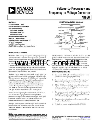
The AD650 converter from Analog Devices provides high‑frequency V/F and F/V operation with typical nonlinearity of 0.002 % at 10 kHz. It supports unipolar, bipolar, or differential inputs and offers an open‑collector output compatible with CMOS or TTL logic. The device is available in several packages, including 14‑lead PDIP, side‑brazed ceramic DIP, and 20‑lead PLCC, with versions meeting MIL‑STD‑883.
Key features include programmable input range via external resistors and capacitors, trimmable input offset, and separate analog and digital grounds to prevent ground loops. The datasheet details specifications, absolute maximum ratings, pin functions, circuit operation, component selection, and ordering information.
| Full‑Scale Frequency Range | 1 MHz |
|---|---|
| Typical Nonlinearity at 10 kHz | 0.002 % typ |
| Quiescent Current | 8 mA |
| Maximum Supply Voltage | 36 V |
The device can tolerate up to 36 V on its supply pins, but higher voltages may cause permanent damage.
Typical nonlinearity at 10 kHz is 0.002 % of full scale.
The AD650 is offered in 14‑lead PDIP, 14‑lead side‑brazed ceramic DIP, and 20‑lead PLCC packages, with MIL‑STD‑883‑qualified versions.