
The AD8372 is a 41dB dynamic range, 1dB gain step programmable dual VGA from Analog Devices. It supports single-ended input and differential output. The device is applied to differential ADC drivers, CMTS upstream direct sampling receivers, CATV modem signal scaling, generic RF/IF gain stages, single-ended to differential conversion, etc.
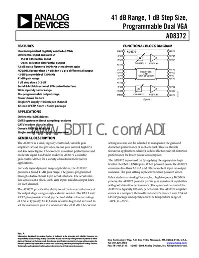
The AD8372 is a dual, digitally controlled variable gain amplifier (VGA) that provides precise gain control, high IP3, and low noise figure. It features differential inputs and outputs, a programmable gain range of 41 dB in 1 dB steps, and an 8‑bit bidirectional SPI interface for setting gain and other parameters.
The device operates from a single 5 V supply, draws 106 mA per channel in active mode, and less than 2 mA in power‑down. It is supplied in a 5 mm × 5 mm 32‑lead LFCSP package and is rated for –40 °C to +85 °C operation. Typical applications include differential ADC drivers, CMTS upstream direct‑sampling receivers, and CATV modem signal scaling.
| Gain range | 41 dB |
|---|---|
| Gain step size | 1 dB |
| Noise figure | 7.8 dB at 100 MHz (max gain) |
| 3‑dB bandwidth | 130 MHz |
| Operating temperature range | -40 °C to +85 °C |
The AD8372 provides a 41 dB gain range.
Gain is programmed through a bidirectional 4‑pin SPI interface that includes clock, latch, data input, and data output lines for each channel.