
This document describes the oscillator system and its operation of Microchip Technology Inc.'s PIC24F series. The oscillator system offers various clock sources and modes, providing high internal operating frequency. It allows software-controlled switching between different clock sources to provide power-saving clock for the CPU. Additionally, it features a fault protection clock monitor that can detect clock failures and safely recover or shut down the application.
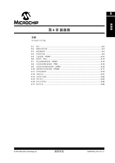
This manual explains the PIC24F oscillator system, which offers up to four selectable external or internal clock sources and eleven different clock modes. It covers the primary oscillator, PLLs, low‑power secondary oscillator, internal fast and low‑power RC oscillators, and the fail‑safe clock monitor.
The document details the control registers (OSCCON, CLKDIV, OSCTUN), clock‑switching procedures, design tips, related application notes, and version history, providing the information needed to configure and troubleshoot the device’s clocking. This manual is written in Chinese.
| Selectable clock sources | 4 external and internal oscillators |
|---|---|
| Clock modes | 11 different modes |
| FRC nominal frequency | 8 MHz |
| LPRC nominal frequency | 31 kHz |
Possible reasons include the device being in sleep mode without a wake‑up source, an incorrect clock mode being selected, an improper power‑up sequence, or incorrect capacitor values on the crystal.
The oscillator circuit gain may be too high, causing the device to run faster than the crystal frequency.
Adjust the value of capacitor C1; using a parallel crystal instead of a series one can also help.
Verify that the oscillator output amplitude is sufficient and that the clock‑mode configuration bits and external capacitors are correct.