
M54/74HC696/697 are high speed CMOS up/down counters fabricated with silicon gate C2MOS technology. They achieve the high speed operation similar to equivalent LSTTL while maintaining the CMOS low power dissipation. The HC696/698 are BCD DECADE COUNTER, and the HC697/699 are 4-BIT BINARY COUNTER. Both devices have register. They count on the positive edge of the counterclock input (CCK) when selected by the ”Counter Mode”. If the input U/D is held ”H”, the internal counter counts up, and held ”L”, counts down. The internal counter’s outputs are stored in the output register at the positive edge of register clock (RCK). The counter
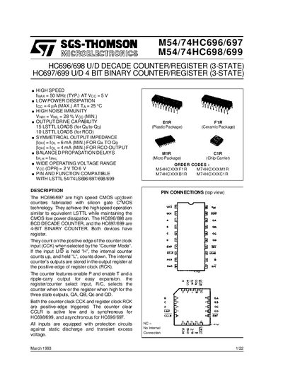
The HC696/697/698/699 family are high‑speed CMOS up/down counters and decade/binary registers compatible with LSTTL logic. They operate up to 50 MHz at 5 V, feature low power dissipation (4 µA max) and high noise immunity (28 % Vcc). The devices offer symmetrical output impedance and can drive multiple LSTTL loads.
The document includes a description of operation, pin description, truth table, block and logic diagrams, timing charts for each variant, mechanical data for the PLCC‑20 package, and ordering codes. It also contains legal notices and company information.
| Noise immunity | VNIH = VNIL = 28 % Vcc (min) |
|---|---|
| Output drive capability (QA‑QD) | 15 LSTTL loads |
| Output drive capability (RCO) | 10 LSTTL loads |
| Package dimensions (A) | 9.78 mm × 9.78 mm (min) / 10.03 mm × 10.03 mm (max) |
| Package dimensions (B) | 8.89 mm × 8.89 mm (min) / 9.04 mm × 9.04 mm (max) |
Each QA‑QD output can drive up to 15 LSTTL loads.