
This is a technical manual for a proportional amplifier module, which introduces the features and characteristics of the product, including the scope of application, order code, functional description, circuit diagram/pin assignment, technical data, output characteristic curve, terminal assignment, unit size, engineering notes/maintenance instructions/additional information.
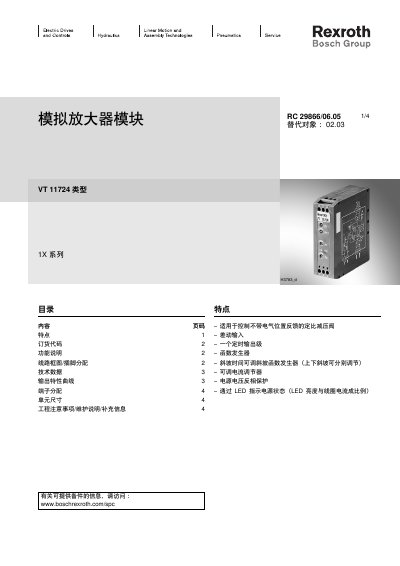
The VT 11724 analog amplifier module is designed for controlling proportional coils of constant‑ratio pressure‑reducing valves without electrical position feedback. It provides differential input, a timing output stage, a function generator, adjustable ramp times, an adjustable current regulator, and LED indication of coil current.
The manual includes a table of contents with sections on features, order code, functional description, wiring diagram and pin assignment, technical data, output characteristic curves, terminal assignment, unit dimensions, and engineering/maintenance notes. Installation is on a DIN‑rail (EN 60715) with six screw terminals, and the module operates from a 24 V DC supply. This manual is written in Chinese.
| Operating Voltage | 24 V DC ±40%/‑10% |
|---|---|
| Power Consumption | 22 VA max |
| Current Consumption | 0.85 A max |
| Maximum Output Current | 800 mA |
| Coil Resistance (20 °C) | 19.5 Ω |
| Clock Pulse Frequency | 200 Hz ±10% |
| Dimensions (W × H × D) | 25 × 79 × 85.5 mm |
| Operating Temperature Range | 0 °C to +50 °C |
| Weight | 0.13 kg |
The module operates from a 24 V DC supply with a tolerance of +40% to –10%.
LED H3 indicates the coil current, with brightness proportional to the current.
The differential input uses U control voltage from 0 to +10 V, with a reference pin tied to ground.