
This manual provides detailed information on the features and characteristics of the C/D series hydraulic cylinders, including installation dimensions, connection methods, torques, flow rates, cylinder weights, etc., as well as ordering codes and related accessory information.
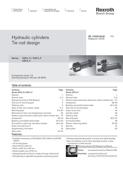
The document describes the CDT3...F, CGT3...F and CST3...F series of tie‑rod hydraulic cylinders, designed for a nominal pressure of 160 bar. It lists 13 mounting types, piston diameters from 25 mm to 200 mm, piston‑rod diameters from 12 mm to 140 mm, and stroke lengths up to 2700 mm. Technical tables give areas, forces, flow rates and cylinder weights for each size and mounting configuration.
Additional sections cover seal versions (M, T, V), guide‑bushing designs, accessories, buckling calculations and end‑position cushioning. The catalogue also provides ordering codes, spare‑part lists and a link to the IHC Designer planning software for quick selection of the optimal cylinder.
| Nominal pressure | 160 bar |
|---|---|
| Minimum recommended pressure | 10 bar |
| Piston diameter range | 25–200 mm |
| Piston rod diameter range | 12–140 mm |
| Maximum stroke length | 2700 mm |
| Seal versions | M, T, V |
The cylinders are designed for a nominal continuous pressure of 160 bar.
Three seal versions are available: M (standard), T (low friction) and V (high‑temperature).
Standard piston diameters range from 25 mm to 200 mm.
The IHC Designer (Interactive Hydraulics Cylinder Designer) is provided for planning and selection.