
The document introduces the PIC16C71X series of 8-bit CMOS microcontrollers, including their features and characteristics. These microcontrollers feature a high-performance RISC CPU, 35 single-word instructions to learn, single-cycle instructions (except for program branches which are two cycles), DC - 20 MHz clock input, DC - 200 ns instruction cycle, etc. Additionally, they have up to 2K x 14 words of Program Memory, up to 128 x 8 bytes of Data Memory (RAM), interrupt capability, an eight-level deep hardware stack, direct, indirect, and relative addressing modes, power-on reset (POR), power-up timer (PWRT) and oscillator start-up timer (OST), watchdog timer (WDT), programmable code-protection, power-saving sleep mode, selectable oscillator options, low-power, high-speed CMOS EPROM technology, fully static design, wide operating voltage range (2.5V to 6.0V), high sink/source current (25/25 mA), commercial, industrial and extended temperature ranges, program memory parity error checking circuitry with parity error reset (PER) (PIC16C715), and low-power consumption.
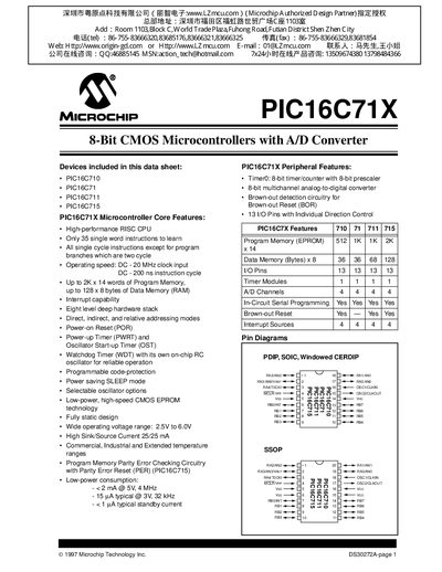
The PIC16C71X family is a low‑cost, high‑performance 8‑bit CMOS microcontroller series with integrated 8‑bit analog‑to‑digital converters. It offers a reduced 35‑instruction RISC core, single‑cycle execution, up to 20 MHz operation, and a variety of power‑saving features such as a watchdog timer, sleep mode, and brown‑out reset. The devices are available in both UV‑erasable and one‑time‑programmable (OTP) versions, supporting a range of oscillator options and packaging styles.
Key hardware resources include up to 2 KB of program memory, up to 128 bytes of RAM, 13 I/O pins, four A/D channels, and an 8‑bit timer/counter module. The datasheet provides detailed electrical characteristics, pin diagrams for DIP, SOIC, and SSOP packages, and information on development tools and programming options.
| Program Memory | up to 2 K × 14 words |
|---|---|
| Data Memory (RAM) | up to 128 × 8 bytes |
| Operating Voltage Range | 2.5 V – 6.0 V |
| Maximum Clock Frequency | 20 MHz |
| I/O Pins | 13 pins |
| A/D Converter Channels | 4 channels (8‑bit) |
| Timer Module | 8‑bit timer/counter with prescaler |
| Power Consumption (typical) | < 2 mA @ 5 V, 4 MHz |
The device can operate up to 20 MHz.
It includes four 8‑bit A/D channels.
The microcontroller works from 2.5 V to 6.0 V.
Each device provides 13 I/O pins.