
This is an instruction sheet for DVP04DA-S module, which introduces the basic functions and use methods of the module.
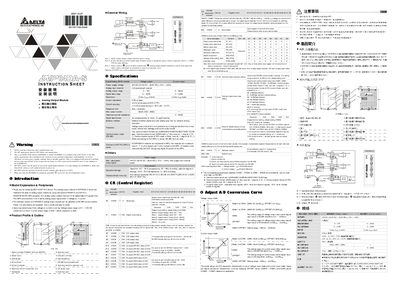
The DVP04DA-S is an analog output module for Delta DVP PLC series. It receives 12‑bit digital data from the PLC and converts it to four analog outputs, selectable as voltage (0‑10 V) or current (0‑20 mA). The module is open‑type, designed for installation in a protected enclosure and can be updated via RS‑485.
The manual covers safety precautions, mechanical mounting, external wiring, RS‑485 communication setup, control register settings for output mode, and detailed technical specifications such as voltage/current ranges, power supply, accuracy, and environmental limits.
| Voltage output range | 0 V ~ +10 V DC (resolution 2.5 mV) |
|---|---|
| Current output range | 0 mA ~ 20 mA (resolution 5 µA) |
| Power supply voltage | 24 V DC (20.4 V ~ 28.8 V DC) |
| Output impedance | ≤ 0.5 Ω |
| Overall accuracy | ±0.5 % FS at 25 °C, ±1 % FS 0 ~ 55 °C |
| Response time | 3 ms per channel |
| Maximum output current | 20 mA |
| Communication mode | RS‑485 (ASCII/RTU, 4.8 kbps‑115.2 kbps) |
The output mode is chosen by wiring: voltage output provides 0 V ~ +10 V DC (2.5 mV resolution) and current output provides 0 mA ~ 20 mA (5 µA resolution). Mode settings can also be programmed via Control Register #1.
The module supports RS‑485 communication with selectable baud rates of 4,800 to 115,200 bps and can operate in ASCII (7 E 1) or RTU (8 E 1) format.