
Key facts
- Brand
- Danfoss
- Model
- FC 360
- Category
- Industrial Supply
- Industry
- Industrial
- Documents
- 3
- Languages
- ZH
- Last added
- 2026-10-12
Start here
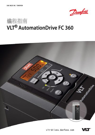
Danfoss VLT AutomationDrive FC 360 Programming Guide
The document serves as a comprehensive programming guide for the VLT AutomationDrive FC 360 variable frequency drive. It details how to access parameters via the local control panel or communication interfaces, covering settings for operation, motor data, braking, limits, and various input/output configurations.
The guide includes an extensive parameter list organized by function groups (e.g., Operation, Load/Motor, Communication), along with definitions of technical terms and abbreviations. It also provides sections on safety requirements, fault diagnosis including warnings and alarms, and specific application settings. This manual is written in Chinese.
Danfoss FC 360 specifications
| Power input | 3‑Phase |
|---|---|
| Control cable voltage (NPN) | 24 V |
| Analog input voltage range | 0‑10 V DC |
| Brake resistor power range | 0.37 – 22 kW |
All Danfoss FC 360 documents by type
Instruction set, parameters and examples for configuring or programming the device.
Questions answered in these manuals
What is the purpose of this programming guide?
This manual provides information on controlling the variable frequency drive, accessing parameters, programming, and troubleshooting.
Who is this guide intended for?
This manual is intended only for qualified personnel who are familiar with the VLT AutomationDrive FC 360.
What analog input types are supported?
The drive accepts voltage inputs of 0‑10 V DC and current inputs of 0‑20 mA or 4‑20 mA.
How should the control cable be terminated?
The control cable must have shielding or armour, and the shield should be grounded as described in the design guide.
How do I start and stop the drive using digital inputs?
Connect the start command to terminal 18 (digital input 8) and the stop command to terminal 27 (digital input 0) as shown in the wiring diagram.
What is required to enable Automatic Motor Identification (AMA)?
The motor must be at standstill; then the AMA algorithm can be activated via the appropriate parameter to automatically identify motor parameters.