
Power Integrations AN-32 application note describing a step-by-step method for designing TOPSwitch-GX offline flyback power supplies.
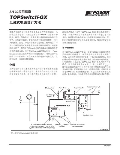
This Power Integrations application note (AN-32) presents a design method for TOPSwitch-GX offline flyback power supplies. It covers the basic circuit topology, the choice of feedback circuit, and a 37-step design flow covering system requirements, device selection, transformer design, and component selection.
The guide provides key formulas, lookup tables, and empirical design guidance for continuous and discontinuous conduction modes, including reflected output voltage, clamp voltage, peak and RMS currents, primary inductance, switching frequency, and external ILIMIT setting. It also notes that PI Expert design software is recommended for TOPSwitch-GX flyback designs. This manual is written in Chinese.
| Document number | AN-32 |
|---|---|
| Document version | Version C 07/04 |
| Document date | July 2004 |
| Design steps | 37 steps |
| Input line frequency | 50 Hz or 60 Hz |
| Default efficiency | 0.8 if no better reference data is available |
| Default loss distribution factor | Z = 0.5 if no better reference data is available |
| Reflected output voltage, multi-output | VOR = 100 V |
| Reflected output voltage, single output | 120 V |
| Maximum output power reflected voltage | VOR = 135 V |
| Bridge rectifier conduction time | tC = 3 ms |
| KP, wide input continuous mode | 0.4 |
| KP, 230 VAC or 115 VAC doubled continuous mode | 0.6 |
| KP, discontinuous mode | 1.0 |
| TOPSwitch-GX drain-source voltage | VDS = 10 V |
| Switching frequency, DIP and SMP packages | 132 kHz |
| Switching frequency, TO-220 package | 66 kHz or 132 kHz |
| ILIMIT reduction factor range | 0.3 ≤ KI ≤ 1.0 |
| Default ILIMIT reduction factor | KI = 1.0 |
| Peak current verification, KI = 1.0 | IP ≤ 0.96 x ILIMIT(min) |
| Peak current verification, KI < 1.0 | IP ≤ 0.94 x ILIMIT(min) |
| Discontinuous mode power derating | Reduce output power by 33% when using selection curves |
| Discontinuous to continuous equivalence | A 10 W discontinuous mode design is equivalent to a 15 W continuous mode design |
| Input bulk capacitor, wide input range | 2~3 mF/Watt output power, VMIN ≥ 90 V |
| Input bulk capacitor, 230 VAC or 115 VAC doubled | 1 mF/Watt output power, VMIN ≥ 240 V |
Power Integrations recommends using PI Expert for TOPSwitch-GX flyback designs. The software includes a knowledge base and optimizes key parameter selection to further shorten design time.
The guide shows four feedback circuits: primary/basic, primary/enhanced, optocoupler/Zener, and optocoupler/TL431. The choice depends on the required output voltage tolerance, load regulation, and line regulation.
The design flow covers 37 steps, from determining system requirements and selecting the feedback circuit to choosing the smallest suitable TOPSwitch-GX, designing the transformer, and selecting the remaining components.
For DIP and SMP packages, set fS = 132 kHz. For TO-220 packages, choose 66 kHz or 132 kHz.