
A description and application manual for the Power Integrations 2SC0535T dual‑channel IGBT driver core.
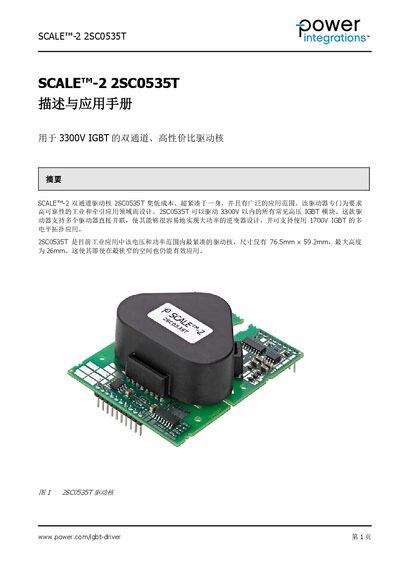
The manual provides an overview of the SCALE‑2 2SC0535T driver core, its features, and typical applications for high‑voltage IGBT modules up to 3300 V. It includes mechanical dimensions, pin definitions, recommended circuits, and operating mode details.
Additional sections cover dead‑time calculation, ordering information, and contact details for technical support worldwide.
| Package size | 76.5 mm × 59.2 mm |
|---|---|
| Maximum height | 26 mm |
| Pin pitch | 2.54 mm (100 mil) |
| Pin cross‑section | 0.64 mm × 0.64 mm |
| VCC supply voltage | 15 V |
| VDC supply voltage | 15 V |
| Maximum IGBT voltage rating | 3300 V |
| Maximum switching frequency | 100 kHz |
| Typical dead‑time range | 0.6 µs – 4.1 µs |
The VCC pin requires a 15 V supply.
The pins are spaced at 2.54 mm (100 mil).
The driver can handle IGBT modules up to 3300 V.
Dead‑time is set by selecting a resistor value for the TB pin; typical values give 0.6 µs to 4.1 µs.