
Parker DC590+ series DC drives cover 15A to 2700A with 32-bit control, multiple I/O, communication options, and integrated DRV system.
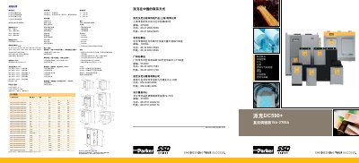
The Parker DC590+ is a family of four-quadrant reversible DC drives (DC590+) and two-quadrant non-reversible drives (DC591+) rated from 15A to 2700A. They feature a 32-bit RISC control architecture, configurable analog and digital I/O, optional feedback interfaces (analog tachogenerator, encoder, fiber optic encoder), and a range of fieldbus communication modules including Profibus, DeviceNet, ControlNet, Ethernet, CANopen, and Modbus. The drives comply with CE (EN50178, EN61800-3), UL508C, and cUL C22.2 No.14 standards.
The DC590+ can be used as a standalone drive or as part of a DRV integrated drive system that includes AC line contactor, fuses, DC fuses, control transformer, and optional motor blower starter. The DRV concept saves panel space, design time, wiring, and component selection. Standard features include dual encoder inputs, function block programming, software-configurable I/O, 12-bit analog resolution, winder control, math and logic functions, controllable field, and S-ramp/digital ramp. The product is supported in over 50 countries with universal input voltage 220-690V, 50/60Hz. This manual is written in Chinese.
| Armature Current Ratings | 15, 35, 40, 70, 110, 165, 180, 270, 380, 500, 725, 830, 1050, 1250, 1450, 1580, 1600, 1950, 2000, 2400, 2700 A |
|---|---|
| Overload Capacity | 200% for 10 seconds, 150% for 30 seconds |
| Armature Voltage (max) | Vac x 1.2 |
| Field Current | 4A (frame 1), 10A (frames 2-3), 30A (frames 4-5), 60A (frames H and 6) |
| AC Supply Voltage Ranges | 110-220V (±10%) all frames; 220-500V (±10%) all frames; 500-600V (±10%) frames 4,5; 500-690V (±10%) frame H; 380-600V (±10%) frame 6; 380-690V (±10%) frame 6 |
| Operating Temperature | 0-45°C (frames 1-3), 0-40°C (frames 4,5,6,H); derate 1% per °C above up to 55°C |
| Altitude Derating | Below 500m normal; above 500m derate 1% per 200m up to 5000m |
| Analog Inputs | 5 channels, 12-bit signed, short-circuit and overvoltage protection |
| Analog Outputs | 3 channels, 12-bit, overvoltage protection |
| Digital Inputs | 9 channels, max 24V, 15mA |
| Digital Outputs | 3 channels, 24V (max 30V), 100mA, short-circuit protection |
| Reference Supplies | +10V DC, -10V DC, +24V DC |
| Communication Options | Profibus, DeviceNet, ControlNet, Ethernet, CANopen, EI Bisynch/Modbus/RS422/RS485 |
| Standards Compliance | CE EN50178, CE EN61800-3, UL508C, cUL C22.2 No.14 |
| Frame 1 Dimensions (HxWxD) | 375 x 200 x 220 mm |
| Frame 2 Dimensions (HxWxD) | 434 x 200 x 292 mm |
| Frame 3 Dimensions (HxWxD) | 485 x 250 x 234 mm |
| Frame 4 Dimensions (HxWxD) | 700 x 253 x 358 mm |
| Frame 5 Dimensions (HxWxD) | 700 x 506 x 358 mm |
| Frame 6 Dimensions (HxWxD) | 715 x 686 x 497 mm |
The DC590+ series covers armature current ratings from 15A up to 2700A across multiple frame sizes.
Supported protocols include Profibus, DeviceNet, ControlNet, Ethernet, CANopen, and EI Bisynch/Modbus/RS422/RS485.
Frames 1-3 operate at 0-45°C, frames 4,5,6,H at 0-40°C, with derating of 1% per °C up to 55°C maximum.
The DRV is a self-contained drive system that includes AC line contactor, AC line fuses, DC fuses (for reversible), control/field fuses, optional motor blower starter, and optional auxiliary control transformer, all mounted beneath the drive to save panel space and wiring time.