
This service manual provides circuit descriptions, troubleshooting procedures, and adjustment instructions for the JRC JRL-2000F HF linear amplifier.
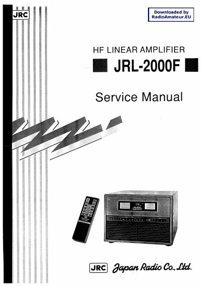
The document serves as a technical guide for maintenance and troubleshooting of the JRL-2000F HF Linear Amplifier. It details the internal configuration, including the power amplifier unit (CAH-377), control circuit (CCB-367), and power supply components.
Key sections include specifications covering operating frequency bands from 1.8 MHz to 29.7 MHz with a rated output of 1 kW PEP. The manual provides specific instructions for adjusting the heat sensor, idle current, APC circuit, ALC circuit, and VSWR meter.
| Operating frequency bands | 1.8 MHz to 29.7 MHz |
|---|---|
| Rated output power (SSB) | 1 kW PEP |
| Output impedance | 50 Q unbalanced |
| Harmonics | -60 dB or less |
| Power supply voltage | 85 to 264 V AC, single-phase |
| Dimensions | 430(W) X 300(h) X 402(0) mm |
The rated output power is 1 kW PEP for SSB and CW with a 100% duty cycle over 24 hours.
The input impedance is 50 Q unbalanced.
Yes, it includes instructions for adjusting the heat sensor, idle current, APC circuit, ALC circuit, and VSWR meter.