
This manual provides step‑by‑step instructions for installing a ground support bracket with a 20° angle, including tools, parts, and assembly sequence.
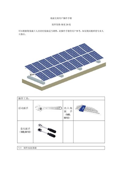
The document is a user operation manual for a ground support bracket configured for a vertical component layout with a 20° angle. It lists required tools, parts, and references construction drawings for each installation step.
Installation steps cover cement foundation preparation, front and rear column mounting, horizontal bar and diagonal support installation, guide‑rail attachment, back‑pull‑rod mounting, and final component placement, with detailed bolt sizes and washer requirements. This manual is written in Chinese.
| Front Column Length | 347 mm |
|---|---|
| Rear Column Length | 850 mm |
| Horizontal Bar Length | 2800 mm |
| Diagonal Support Length | 972 mm |
| Guide Rail Length | 3100 mm |
| Back Pull Rod Dimensions | 41 × 21 × 2885 mm |
The required tools are an adjustable wrench, hex wrenches (M8, M10), and socket wrenches (M8, M10).
The cement foundation is poured on site according to the latest construction drawing HYJ02, with embedded bolts as shown.
Guide rails are fixed with M10×35 inner‑hex bolts, a flat washer, a spring washer, and an M10 square nut.
After leveling, all bolts should be tightened securely.