
User manual for an FT232RL-based USB to serial UART module with selectable 3.3 V or 5 V TTL level, covering features, applications and setup.
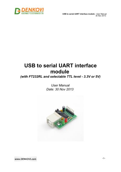
This six-page manual describes a USB to serial UART interface module built around the FT232RL chipset. The module converts between a computer USB port and a serial UART with TTL level of 3.3 V or 5 V, selected with a jumper, and it appears on the computer as a Virtual Com Port (VCP). It has a USB port, Rx and Tx LEDs, and the lines mapped are CTS, GND, RXD, VCC, RTS and TXD. The board measures 41 mm x 25 mm x 14 mm.
The document lists application examples such as upgrading legacy peripherals to USB, interfacing MCU/PLD/FPGA designs to USB, USB smart card readers, instrumentation and industrial control. Installation is covered in three steps: install the FTDI VCP drivers (a download link to the FTDI website is given, with driver availability listed for Windows, Linux, Mac OS and other systems), swap the Rx and Tx lines when connecting to the target, then plug the converter into the computer and confirm that it appears as a virtual com port. Links to FTDI installation guides are included.
| Chipset | FT232RL |
|---|---|
| Interface | Computer USB port to serial UART (TTL) |
| TTL level | Selectable 3.3 V or 5 V via jumper |
| Mapped lines | CTS, GND, RXD, VCC, RTS, TXD |
| Indicators | Rx and Tx LED |
| Size | 41 mm x 25 mm x 14 mm |
| Operating mode on host | Virtual Com Port (VCP) |
You must install the FTDI VCP drivers first; the manual points to the FTDI website download page for them.
The features page lists Windows, Linux and Mac, and the installation step additionally lists Windows CE.NET (version 4.2 and greater) and Android.
The Rx and Tx lines of the two devices must be swapped, as shown in the manual's figure.
Connect the converter to your computer and check whether it appears as a virtual com port.