
The DM542 stepper motor driver manual provides specifications, wiring connections, installation guidelines, and parameter settings for the device.
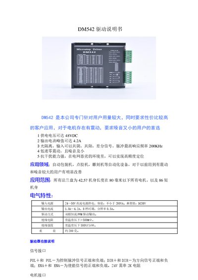
The DM542 driver is designed for applications that require low vibration and noise, such as automatic packaging machines, glue dispensers, and engraving equipment. It operates from a DC supply up to 48 V and can deliver a peak output current of up to 4.2 A, with features like optical isolation, high‑frequency pulse response, and strong EMI resistance.
The manual covers electrical characteristics, signal and motor interfaces, power connections, indicator LEDs, installation dimensions, and detailed parameter settings including current limits and micro‑stepping configuration. Wiring diagrams and switch settings are provided to help users configure the driver for their specific stepper motor and application. This manual is written in Chinese.
| Supply voltage | 24‑50 V DC |
|---|---|
| Peak output current | 4.2 A |
| Adjustable output current range | 1.0 A – 4.2 A, 8 steps |
| Current resolution | 0.5 A |
| Dimensions (L×W×H) | 118 mm × 75.5 mm × 34 mm |
| Weight | ≈200 g |
| Insulation resistance | > 500 MΩ |
| Insulation strength | 500 V/min |
| Maximum pulse response frequency | 200 kHz |
| Power indicator LED | Green (steady when powered) |
| Fault indicator LED | Red (steady on fault) |
The driver should be powered with a DC voltage between 20 V and 50 V.
A fault is cleared by power‑cycling the driver and re‑enabling it.
The output current is set with an 8‑position DIP switch, allowing selection from 1.0 A to 4.2 A.