
This Altera handbook explains reset signals, power‑down signals and sequence procedures for Stratix IV transceiver channels.
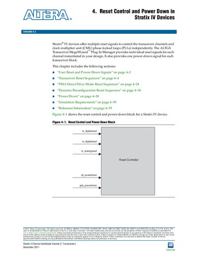
The handbook describes the reset control and power‑down architecture for Stratix IV devices, including the individual reset signals for each transceiver channel and the block‑level power‑down signals. It provides tables of signal definitions, pulse‑width requirements, and the blocks affected by each reset or power‑down signal.
Detailed reset sequences are given for various functional modes such as XAUI, PCIe, and basic bonded configurations. The document also covers dynamic reconfiguration reset procedures, optional gxb_powerdown usage, and simulation requirements for designers implementing these signals in their designs.
| tx_digitalreset minimum pulse width | two parallel clock cycles |
|---|---|
| rx_digitalreset minimum pulse width | two parallel clock cycles |
| rx_analogreset minimum pulse width | two parallel clock cycles |
| gxb_powerdown minimum pulse width | 1 µs |
| pll_powerdown function | powers down the CMU PLLs that provide high‑speed serial and low‑speed parallel clocks |
The tx_digitalreset signal requires a minimum pulse width of two parallel clock cycles.
Unused transceiver channels can be powered down using the optional gxb_powerdown signal, which has a minimum pulse width of 1 µs.
If the gxb_powerdown port is not instantiated, the tx_digitalreset, rx_digitalreset, and rx_analogreset signals must be asserted appropriately.
The pll_powerdown signal powers down the CMU PLLs that generate high‑speed serial and low‑speed parallel clocks for the transceiver channels.