
This manual introduces the use of the water supply control board SWS.
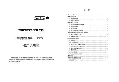
This manual provides step‑by‑step instructions for installing the SWS water‑supply control base board used with the SAMCO‑vm05 inverter. It includes preparation, mounting, wiring diagrams, terminal descriptions, and the overall wiring layout for the water‑supply system.
The document also details the software function codes, operation modes, PID control, relay‑output functions, and safety precautions required for reliable operation of the water‑pump system. This manual is written in Chinese.
| Number of relays | 8 |
|---|---|
| Maximum motor connections | 7 |
| Minimum switching capacity | 10 mA |
| Electrical life | ≥100 000 cycles |
| Mechanical life | ≥10 000 000 cycles |
| Contact resistance | ≤0 Ω |
| Coil current limit | ≤400 mA |
| Relay response time | ≤15 ms |
The board contains eight relays, each providing contact outputs for the water‑supply system.
Up to seven motors can be connected to the SWS board.
Each relay can switch a minimum current of 10 mA.
The coil current must not exceed 400 mA.