
This document describes the FAN6248ADPGEVB evaluation board user's manual. The evaluation board utilizes NCP1616 PFC front stage, NCP13992 current mode LLC power stage, and FAN6248 secondary side synchronous rectification to achieve high efficiency.
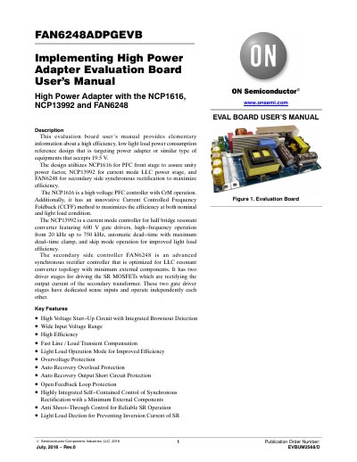
This document provides elementary information about the FAN6248ADPGEVB, a high efficiency, low light load power consumption reference design targeting power adapters that accept 19.5 V input. The design utilizes the NCP1616 for the PFC front stage, the NCP13992 for the current mode LLC power stage, and the FAN6248 for secondary side synchronous rectification to maximize efficiency.
The manual details the circuit description, including the operation of the PFC front stage with integrated high voltage start-up and Current Controlled Frequency Foldback (CCFF) topology. It also covers the LLC controller features such as zero voltage switching (ZVS) and dynamic self supply, as well as the synchronous rectifier controller optimized for LLC resonant converter topology with minimum external components. Technical specifications for the board, transformers, and measuring results for efficiency and power factor are included.
| Input Voltage | 90 - 264 VAC |
|---|---|
| Output Voltage | 19.3 VDC |
| Maximum Output Current | 12.4 A |
| Output Power | 240 W |
| Operating Frequency of LLC | 100 - 110 kHz |
| System Efficiency (110VAC @ Full Load) | 93.2 % |
| System Efficiency (220VAC @ Full Load) | 95.1 % |
| Board Dimension | 170x100x30 mm |
| PCB material | FR4 |
| Copper Thickness | 2 oz |
The board accepts an input voltage range of 90 to 264 VAC.
The maximum output power is 240 W.
The design utilizes NCP1616 for PFC, NCP13992 for the LLC power stage, and FAN6248 for secondary side synchronous rectification.