
This manual describes how to use digital input.
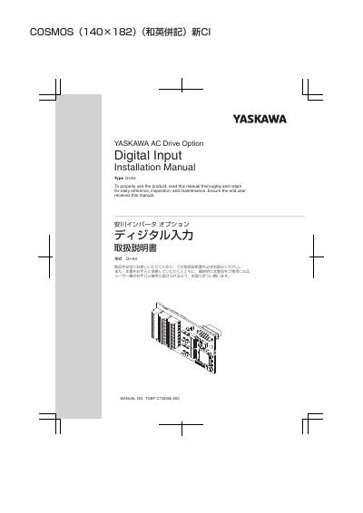
This manual (MANUAL NO. TOBP C730600 80C) explains how to install the Yaskawa AC Drive Option DI-A3 Digital Input on a drive and set the related drive parameters. The DI-A3 lets the user set the drive frequency/speed reference using binary coded digital inputs, with binary 16-bit 4-digit, 12-bit 3-digit, or 8-bit 2-digit BCD input.
The document covers preface and safety, overview and compatible products, receiving and package contents, option components and terminal blocks TB1, TB2 and TB3, the installation procedure with wire gauges and tightening torques, related parameters, troubleshooting, European standards, and specifications.
| Input type | +24 Vdc 8 mA isolated input |
|---|---|
| Binary input (BCD) | 16-bit, 4-digit BCD input |
| Binary input (BCD), 12-bit | 12-bit, 3-digit BCD input |
| Binary input (BCD), 8-bit | 8-bit, 2-digit BCD input |
| Compatible drive series | A1000, L1000A, U1000, U1000L, GA700, GA800, CR700, CH700 (all models) |
| Terminal screw size and tightening torque | M2, 0.22 to 0.25 N·m (1.95 to 2.21 in·lb) |
| Recommended wire gauge (stranded, bare cable) | 0.75 mm2 (18 AWG) |
| Applicable ferrule-type terminal gauge | 0.25 to 0.5 mm2 (24 to 20 AWG) |
It allows the user to set the drive frequency/speed reference using binary coded digital inputs.
A1000, L1000A, U1000, U1000L, GA700, GA800, CR700 and CH700 drives, all models.
On A1000, U1000, GA700, GA800, CR700 and CH700 set b1-01 or b1-15 to 3; on L1000A and U1000L set b1-01 to 3.
The input is a +24 Vdc 8 mA isolated input.