
This is the manual for DC2244A provided by Linear Technology Corporation.
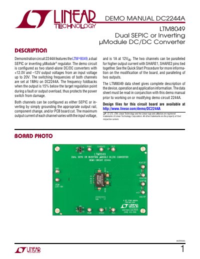
This manual provides instructions for setting up and operating the DC2244A demonstration circuit, which includes the LTM8049 dual SEPIC or inverting µModule DC/DC converter. The board is configured for two independent DC/DC converters with +12.0V and -12.0V outputs from an input voltage up to 20V. Switching frequencies are set at 1MHz, with frequency foldback for protection during faults or overloads. The manual includes a quick start procedure, performance specifications, parts list, and schematic diagrams for modification and paralleling configurations. This manual is written in Chinese.
| Input Supply Range | 2.8V to 18V |
|---|---|
| Switching Frequency | 1 MHz |
| Output Voltage Channel 1 | +12.0V |
| Output Voltage Channel 2 | -12.0V |
| Maximum Output Current | 1A at 12V IN |
| Output Ripple Channel 1 | 60 mV |
| Output Ripple Channel 2 | 20 mV |
| Efficiency Channel 1 | 82% |
| Efficiency Channel 2 | 81.0% |
The input voltage range is 2.8V to 18V.
The maximum output current is 1A at 12V input.
Cut the copper along C5 and short the other terminal of C5 to ground. Remove resistor R9 and replace resistor R10 with proper values.