
This is a dual channel ideal diode controller board that can provide up to 20 A of current and operate over a 4.5 V to 28 V range.
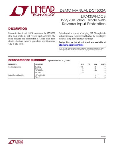
This demo manual describes the DC1502A circuit board featuring two independent LTC4359 ideal diode circuits. Each channel supports up to 20A, with voltage ratings from 4.5V to 28V. The board includes test pads for modifying the circuit or connecting external power stages. It also details voltage drops, current limitations, and operational procedures for testing and modifying the circuit.
The manual explains how to operate the board with two power supplies, how to test voltage drops without high-power loads, and how to safely shut down the circuit. It includes specifications for voltage limits, current capabilities, and circuit resistances, along with practical tips for minimizing losses and heat dissipation during operation.
| Input Voltage Limits (Operating) | 4.5V to 28V |
|---|---|
| Output Current Capability (VIN > 8V) | 20A |
| VIN-VOUT Voltage Limit | -60V |
| Quiescent Current (Shutdown) | ~14µA |
Each channel is capable of carrying 20A, provided the LTC4359s are enabled.
The board operates over a 4.5V to 28V range.
Turn off the 20A supply first, then turn off the 12V supply to prevent passing 20A through the body diodes.