
The current feedback operational amplifier (CFB) is a very popular topology that offers a number of unique advantages, including no slew rate limit, high gain bandwidth product, and low input capacitance. This article introduces the simplified circuit and model of the CFB op amp and derives its transfer function.
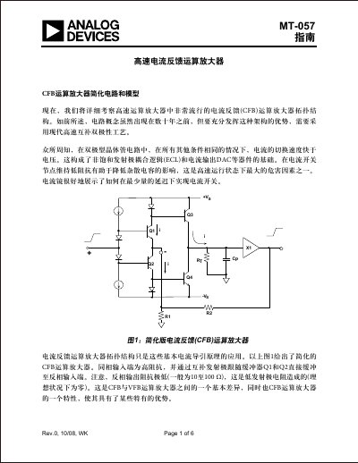
This document provides a detailed examination of the current feedback (CFB) operational amplifier topology. It contrasts CFB with voltage feedback (VFB) architectures, explaining how low input impedance at the inverting terminal allows for faster switching speeds compared to bipolar transistor circuits used in other logic families.
The guide includes simplified circuit diagrams and models, along with Bode plot analysis to demonstrate closed-loop bandwidth calculations. It specifically highlights the performance of modern CFB amplifiers like the AD8011, noting its advantages such as high bandwidth independent of gain settings and low power consumption due to a two-stage gain configuration. This manual is written in Chinese.
| Supply Current (AD8011) | 1mA |
|---|---|
| Bandwidth (G = +1, AD8011) | 300MHz |
| Slew Rate (AD8011) | 2000 V/µs |
| Settling Time to 0.1% (G = +2, AD8011) | 29ns |
| Differential Gain Error (AD8011) | 0.02% |
CFB op amps have a very low input impedance at the inverting terminal (typically 10 to 100 ohms), whereas VFB op amps rely on voltage ratios.
No, the closed-loop bandwidth depends on the internal pole capacitance and the external feedback resistor, remaining independent of the gain-setting resistor R1.
They offer higher total bandwidth and lower distortion for the same power consumption compared to traditional single-stage designs.