
The RM10 - RM10Z silicon rectifier diodes have high current capability, high surge current capability, high reliability, low reverse current and low forward voltage drop.
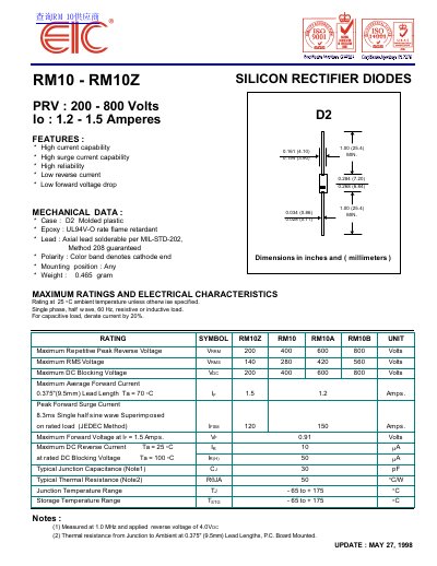
This document provides technical specifications for the EIC RM10 and RM10Z series of silicon rectifier diodes. It covers features such as high current capability and low forward voltage drop, along with mechanical details including the D2 molded plastic case and UL94V-0 flame retardant rating.
The datasheet details maximum ratings and electrical characteristics for various models (RM10, RM10A, RM10B, RM10Z) at 25°C ambient temperature. It includes data on repetitive peak reverse voltage, average forward current, and peak forward surge current, accompanied by derating curves and typical characteristic graphs for forward and reverse operation.
| Maximum Repetitive Peak Reverse Voltage (VRRM) | 200 - 800 Volts |
|---|---|
| Maximum Average Forward Current (IR) | 1.2 - 1.5 Amps |
| Maximum Forward Voltage (VF) | 0.91 Volts |
| Maximum DC Reverse Current (IR) | 10 µA |
| Typical Junction Capacitance (Cj) | 30 pF |
| Typical Thermal Resistance (RJA) | 50 °C/W |
| Junction Temperature Range (TJ) | -65 to +175 °C |
| Case Type | D2 Molded plastic |
The lead length is 0.375 inches (9.5mm).
The maximum ambient temperature for the rated average forward current is 70°C.
Polarity is indicated by a color band that denotes the cathode end.