
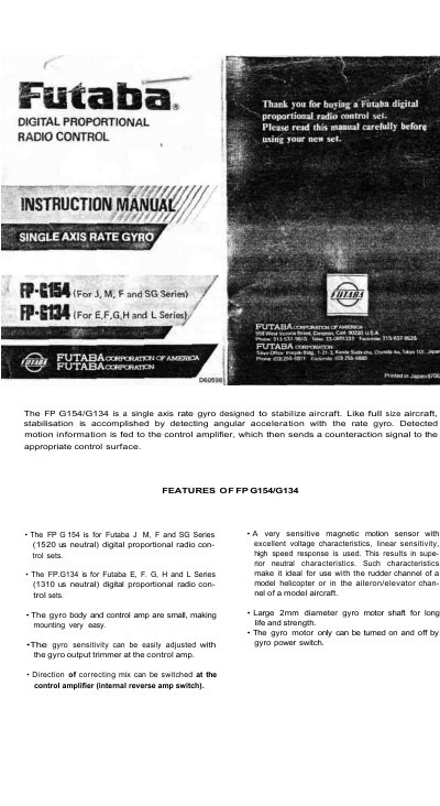
This is the instruction manual for the Futaba FP-G154 and FP-G134 single axis rate gyros, used to stabilize model aircraft and helicopters. The gyro detects angular motion and feeds the information to the control amplifier, which sends a counteraction signal to the appropriate control surface. The FP-G154 is intended for Futaba J, M, F and SG Series (1520 us neutral) digital proportional radio control sets, while the FP-G134 is for E, F, G, H and L Series (1310 us neutral) sets.
The manual lists the features of the two gyros, gives ratings, explains the connections to the receiver and servo, and describes installation of the gyro body and control amplifier with double-side adhesive tape. It also covers adjustment of the gyro output trimmer, the power supply arrangement shared with the receiver and servos, and precautions.
| Power supply voltage | 4.8 V shared with receiver |
|---|---|
| Current drain | Motor: 100 mA, Amplifier: 20 mA (at 4.8 V) |
| Gyro body dimensions | 1.57 x 1.65 x 1.60 in. (42 x 34 x 39 mm) |
| Control amplifier dimensions | 1.06 x 1.89 x .63 in. (27 x 48 x 16 mm) |
| Gross weight | 3.6 oz. (102 g) |
| Gyro motor shaft diameter | 2 mm |
The FP-G154 is for Futaba J, M, F and SG Series (1520 us neutral) sets, while the FP-G134 is for Futaba E, F, G, H and L Series (1310 us neutral) sets.
Connector (A) goes to the receiver channel to be stabilized and connector (B) goes to the servo for that channel.
The G154/G134 uses the same power supply as the receiver and servos.
Use the gyro output trimmer at the control amplifier to set sensitivity between 0% and 100%; for a model helicopter the manual suggests starting at graduation 7 with a small flat blade screwdriver.