
This document describes the features and characteristics of the M24C16, M24C08, M24C04, M24C02, and M24C01 serial EEPROM chips that support the I²C bus. These chips have a two-wire I²C serial interface, support a 400kHz protocol, operate at a single supply voltage of 2.5V to 5.5V or 1.8V to 5.5V, and have features such as write control input, byte and page write (up to 16 bytes), random and sequential read modes, self-timed programming cycle, automatic address incrementing, enhanced ESD/latch-up protection, over 1 million write cycles, and over 40-year data retention.
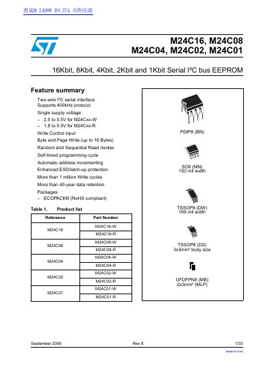
The document details the electrical characteristics, operating modes, and pin configurations of the M24C16, M24C08, M24C04, M24C02, and M24C01 EEPROM devices. These devices are organized as 2048/1024/512/256/128 x 8 bits and utilize a two-wire serial interface comprising a bi-directional data line (SDA) and a clock line (SCL). The protocol supports a maximum frequency of 400kHz.
| Memory Organization (M24C16) | 2048 x 8 |
|---|---|
| Memory Organization (M24C08) | 1024 x 8 |
| Memory Organization (M24C04) | 512 x 8 |
| Memory Organization (M24C02) | 256 x 8 |
| Memory Organization (M24C01) | 128 x 8 |
| Maximum Protocol Frequency | 400kHz |
| Data Retention | More than 40-year |
| Write Endurance | More than 1 million Write cycles |
The operating supply voltage for M24Cxx-W devices ranges from 2.5V to 5.5V.
The operating supply voltage for M24Cxx-R devices ranges from 1.8V to 5.5V.
When Write Control is driven High, write operations are disabled to the entire memory array.