
This document is the electronic speed control operating instructions, which introduces the use of electronic speed control, precautions, installation methods and so on
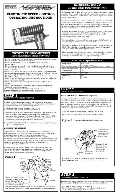
This manual provides operating instructions for the DuraTrax Spike Electronic Speed Control (ESC). It details important precautions regarding battery voltage limits and moisture protection. The guide covers proper mounting techniques to minimize radio interference and overheating, including specific placement recommendations for off-road vehicles with metal or graphite chassis.
The document includes step-by-step hook-up instructions for installing motor capacitors and connecting the ESC to various receiver brands such as Futaba, Airtronics, Hitec, and JR. It also explains how to set transmitter adjustments like neutral, high speed, and coast brake. A troubleshooting section addresses common issues such as no brakes, overheating, or radio glitches.
| Voltage Input | 5 to 7 Cells |
|---|---|
| Case Size | 1.65"x.82"x.67" |
| Weight | 1.27 oz (36g) |
| Max Constant Current | 150 amps |
| Fuse Rating | 30A |
| BEC Voltage | 5.6 volts |
Never use more than 7 cells (8.4 volts total) in the main battery pack.
It can be directly connected to Futaba J, Airtronics Z, Hitec S, or JR receivers.
Solder a 0.1uF capacitor between the positive brush tab and ground tab, and another between the negative brush tab and ground tab.