
This document describes the common requirement of executing a relative move in operating a stepper motor system. The move is usually specified as a fixed number of basic motor steps in the clockwise or counter-clockwise direction. It is common practice to execute this move along a trapezoidal shaped velocity vs. time profile. This profile is determined by the number of steps to be moved and the required accel, decel, and peak speed. Very often system designers require that a move be made in the shortest time possible and in these cases the accel, decel and peak speed are set to the maximum that the system can achieve. Given the move distance, accel, decel, and peak speed requirement, a profile can be determined. Since the control structure of the practispin software is designed such that the velocity and accel/decel rate can be changed at will, the task of pre-calculating the velocity profile boils down to determining the position values where operation switches from accel to constant speed and then from constant speed to decel. Since this is a relative move, we can assume that motion starts at position = 0, time = 0, and velocity = 0.
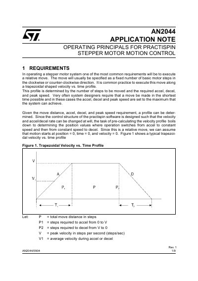
The document details the requirements for executing relative moves in a stepper motor system using a trapezoidal or triangular velocity vs. time profile. It provides specific mathematical formulas to calculate position values where the system switches between acceleration, constant speed, and deceleration phases based on total move distance and rate constraints.
Furthermore, it describes the Practispin control scheme which relies on a 20 kHz interrupt service routine (ISR) running every 50 microseconds. The note outlines motion simulation formulas used within this ISR to update velocity and position variables in real-time using multiple precision integers with a fixed binary point representation.
The system uses a 20 kHz interrupt that invokes an Interrupt Service Routine on a fixed time interval of 50 microseconds.
The maximum value for velocity (SPD) is equal to 20,000 steps per second.
The maximum position value represents 327.68 rotations for a motor with 200 steps per rotation.