
This document describes a device for overvoltage and overcurrent protection for main distribution frames and line cards, including a primary protection level and suitability. The document also explains the protection concept and analyzes the performance of CLP270M when facing different surges as described in the BELLCORE GR 1089 recommendations.
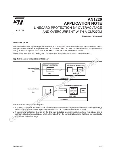
The document describes the evolution of Subscriber Line Interface Circuit (SLIC) protection, highlighting how the CLP270M combines programmable voltage features with overcurrent detection and a Failure Status output. It details the device's role in primary protection on line cards to handle high-energy disturbances like lightning transients.
The text provides specific application circuits for both ringing mode and speech mode. In ringing mode, the CLP270M operates as a bidirectional overvoltage protector at +/- 270V. In speech mode, it works with an external voltage reference device to clamp surges, with activation currents adjustable via a sense resistor (Rsense). The note also covers failure status diagnostics and test results based on Bellcore standards.
| Overvoltage protection level (ringing mode) | +/- 270 V |
|---|---|
| Activation current adjustment method | Rsense resistor |
In normal conditions, it operates idle; if an overvoltage reaches +/- 270 V between TIP/RING and GND, it short-circuits the line to GND.
The device provides a Failure Status (FS) signal on pin 1 when short-circuiting the line, which can drive an LED or logic circuitry.