
This application note provides a step-by-step procedure to design a customized tag antenna for 13.56 MHz RFID applications.
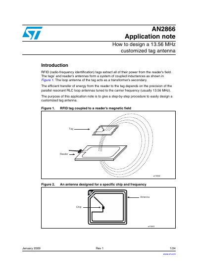
This document explains how to design a customized tag antenna for 13.56 MHz RFID systems. It details the equivalent electrical circuits of the chip and antenna, providing formulas to calculate the required coil inductance based on the chip's tuning capacitance and the target frequency. The note also includes a design procedure using a specific software tool and tools to produce antenna coil prototypes.
| Example Inductance (28.5 pF) | 4.83 µH |
|---|---|
| Example Inductance (23.5 pF) | 5.86 µH |
| Example Inductance (97 pF) | 1.42 µH |
| Example Inductance (64 pF) | 2.15 µH |
To give a step-by-step procedure to easily design a customized tag antenna.
The antenna is designed for a carrier frequency of 13.56 MHz.
The calculated antenna coil inductance is 6.56 uH.
A capacitance of 64 pF is used for short-range applications at 14.40 MHz.