
This application note explains how to design a transition-mode PFC pre-regulator using the L6563S and L6563H. The L6563S and L6563H are the latest devices from STMicroelectronics for low and middle power applications such as lamp ballasts, high-end adapters, flatscreen TVs and monitors, PC power supplies, and all SMPS requiring harmonics reduction. The L6563S is a current-mode PFC controller operating in transition mode (TM) and is packaged in the same SO14 pinout as its predecessor L6563, offering improved performance and additional functions. The L6563H is the SO16 pinout version, embedding the same features as the L6563S with the addition of a high-voltage startup power source. These functions make the L6563H especially suitable for applications that need to be compliant with energy-saving regulations and where the PFC pre-regulator works as the master stage without an auxiliary SMPS.
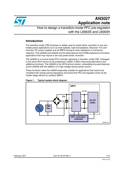
This document provides a comprehensive guide on designing power factor correction (PFC) pre-regulators using STMicroelectronics' L6563S and L6563H controllers. It focuses on the transition-mode (TM) technique, which is widely used for applications such as lamp ballasts, adapters, and PC power supplies to meet harmonics reduction regulations. The note details the operation of the boost topology in transition mode, highlighting its advantages in cost and component count compared to fixed-frequency PWM methods.
The DC output voltage must be higher than the maximum expected line peak voltage, which is typically 400 VDC for 230 V or wide-range mains applications.
Transition-mode operation is typically used in a lower power range up to 250 W.
The bandwidth of the error amplifier should be narrow enough, specifically below 20 Hz.