
This document describes the EVAL2293Q demonstration board for the L2293Q push-pull four channel driver with integrated diodes. The L2293Q is designed to drive inductive loads such as DC and stepping motors, or relays and solenoids. The board implements a typical application which can be used as a reference design to drive two-phase bipolar stepper motors with currents up to 0.6 A DC, multiple DC motors and a wide range of inductive loads. Housed in a QFN 5 x 5 mm 32-lead package, the small footprint of the L2293Q makes the PCB very compact (24.5 x 24.5 mm).
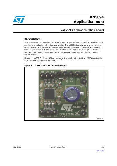
The document details the EVAL2293Q demonstration board, which serves as a reference design for driving two-phase bipolar stepper motors with currents up to 0.6 A DC, as well as multiple DC motors and various inductive loads. The board utilizes the L2293Q chip, housed in a compact QFN 5 x 5 mm 32-lead package, to implement a typical application circuit.
| Supply voltage range (VS) | VSS to 36 V |
|---|---|
| Logic supply voltage range (VSS) | 2.8 to 36 V |
| RMS output current rating | Up to 0.6 A |
| Switching frequency | Up to 50 kHz |
| Thermal resistance junction-to-ambient | 42 °C/W |
The board is designed to drive inductive loads such as DC and stepping motors, relays, and solenoids.
It implements a typical application used as a reference design to drive two-phase bipolar stepper motors.
When LOW, the enable pins switch off the corresponding output power transistors.