
This document describes the evaluation board of the DMOS fully integrated stepper motor driver L6228Q. The board implements a typical application that can be used as a reference design to drive two-phase bipolar stepper motors with currents up to 1 A DC. Thanks to the small footprint of the L6228Q (QFN 5 x 5 mm, 32-lead) the PCB is very compact (27 x 32 mm).
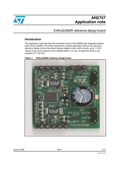
This document describes the EVAL6228QR reference design board, which implements a typical application for driving two-phase bipolar stepper motors using the L6228Q DMOS fully integrated stepper motor driver. The board is designed to support currents up to 1 A DC and features a compact PCB footprint of 27 x 32 mm.
The note provides a detailed description of the demonstration board, including a table of pin connections for the L6228Q chip, recommended electrical specifications such as supply voltage and operating temperature, and a part list for the components used on the board. It also explains the function of specific components like the charge pump circuit and overcurrent protection circuitry.
| Supply voltage range | 8V to 52 VDC |
|---|---|
| RMS output current rating | upto 1.4A |
| Switching frequency | up to 100 kHz |
| Voltage reference range | 0 to +5V |
| Operating temperature range | -25 °C to +125 °C |
| Thermal resistance junction to ambient | 42 °C/W |
The board can drive stepper motors with currents up to 1 A DC.
The PCB is very compact with a footprint of 27 x 32 mm.
The DIAG pin signals an overcurrent or overtemperature event when it goes low.