
This application note describes the demonstration board of the DMOS dual full-bridge L6227Q designed for motor control applications. The board implements a typical application that can be used as a reference design to drive two-phase bipolar stepper motors with currents up to 1A DC, multiple DC motors and a wide range of inductive loads. Thanks to the small footprint of the L6227Q (QFN 5 x 5 mm, 32-lead) the PCB is very compact (27 x 32 mm).
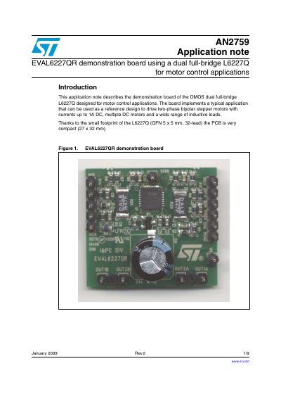
The document details the EVAL6227QR demonstration board, which utilizes the DMOS dual full-bridge L6227Q IC designed for driving two-phase bipolar stepper motors with currents up to 1A DC, as well as multiple DC motors and various inductive loads. The board features a compact PCB design measuring 27 x 32 mm.
| Supply voltage range (VS) | 8 to 52 Vdc |
|---|---|
| RMS output current rating (OUTx) | upto 1.4A |
| Switching frequency | up to 100 kHz |
| Input and enable voltage range | 0 to +5V |
| Operating temperature range | -25 to +125°C |
It is designed for motor control applications, specifically driving two-phase bipolar stepper motors with currents up to 1A DC.
The recommended value for the RMS output current rating (OUTx) is up to 1.4A.
It can obtain a variable voltage by low-pass filtering a PWM output of a microcontroller.