
This document describes the characteristics and performance of a 90 W wide range input AC-DC adapter based on asymmetrical half-bridge topology (AHB). The converter comprises a two-stage approach: a PFC front-end stage using the L6563 TM PFC controller and a DC-DC stage that implements the asymmetrical half-bridge (AHB) topology driven by the L6591, the new PWM controller dedicated to this architecture. Thanks to the AHB topology, the system offers good electrical performance (EPA 2.0 compliant) with a low-voltage and high-current output (12 V - 7.5 A). The order code for this demonstration board is EVL6591-90WADP.
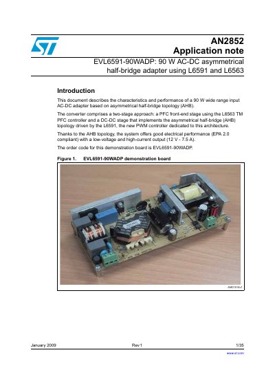
The document details a 90 W wide range input AC-DC adapter based on an asymmetrical half-bridge (AHB) topology. The system utilizes an L6563 PFC controller for the front-end stage and an L6591 PWM controller for the DC-DC stage, delivering a 12 V output at up to 7.5 A.
| Input mains range | 88 ~ 264 Vrms |
|---|---|
| Output voltage | 12Vdc + 2% |
| Output current | 7.5 A |
| No-load consumption | below 0.35 W |
| PCB size | 174x78mm |
The order code for this demonstration board is EVL6591-20WADP.
The adapter provides a 12 V DC output with a current range of 2% to 7.5 A.
The adapter accepts an input mains voltage ranging from 88 to 264 Vrms.
The PCB measures 174x78mm.