
This document describes all features of the PM6641 demonstration board, including main features, demonstration kit schematic, bill of material, component assembly and layout, I/O interface, etc.
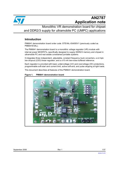
The document details the features, schematic, bill of materials, assembly layout, and configuration options for the PM6641 evaluation board. The board utilizes a monolithic voltage regulator module designed to supply DDR2/3 memory and chipset power in space-constrained portable systems.
Key sections include instructions on setting up jumpers for output dividers (VDDQ, VTT), phase control, and current limiting. It also provides test setup diagrams and results demonstrating soft-start behavior, load regulation, efficiency, fault management (OVP, UVP, thermal shutdown), and transient responses.
The switching section accepts an input voltage range from 2.7 V to 5.5 V.
The board integrates three independent buck converters, a +2 Apk LDO linear regulator, and a +15 mA low-noise buffered reference.
The demonstration board has an order code of STEVAL-ISAQ50V1.