
This document provides technical notes on using Analog Devices' DSP components and development tools, including the programmable input/output flag pins on the ADSP-21161 SIMD SHARC processor. The IOFLAG register is used to control these additional input/output flag pins, and example assembly instructions are provided.
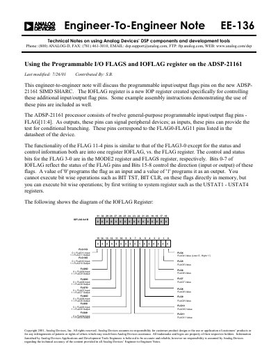
This document provides technical notes on using the programmable input/output flags pins on the new ADSP-21161 SIMD SHARC processor. It details the functionality of the twelve general-purpose programmable input/output flag pins (FLAG[11:4]), which can signal peripheral devices as outputs or provide conditional branching tests as inputs.
The text describes the IOFLAG register, a new IOP register created specifically for controlling these additional pins. It includes definitions for symbolic constants and macros in the VisualDSP++ tools header file to program these flags. The document also covers system design considerations regarding clock ratios (2:1, 3:1, 4:1) and provides examples of assembly instructions with necessary NOPs to prevent output overruns when setting or toggling flag pins.
The IOFLAG register is a new IOP register created specifically for controlling the additional input/output flag pins (FLAG[11:4]).
A value of '0' programs the flag as an input and a value of '1' programs it as an output.
NOPs are required to ensure overruns do not occur because core stalls do not happen when writing to FLAG pins synchronized to the slower DSP system clock.