
This document describes the design, operation, and test results of the ADP1876-EVALZ evaluation board. The input range for this evaluation board is 10 V to 20 V, and the two regulated output voltages are set to 5 V (VOUT1) and 1.8 V (VOUT2) with a maximum 13 A output current. The power components, such as the MOFSETS, inductors, and bulk input and output capacitors, were chosen to yield a low system cost and good efficiency.
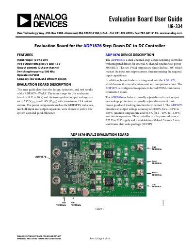
This user guide details the design, operation, and test results of the ADP1876-EVALZ evaluation board. The board features an input voltage range of 10 V to 20 V and provides two regulated output voltages: 5 V (VOUT1) and 1.8 V (VOUT2), with a maximum output current of 13 A per channel. The design utilizes power components such as MOSFETs, inductors, and capacitors to achieve a low-cost and efficient solution.
| Input voltage range | 10 V to 20 V |
|---|---|
| Output voltages | 5 V and 1.8 V |
| Output current | 13 A per channel |
| Switching frequency | 600 kHz |
| Operating mode | PWM |
| Package type | 32-lead LFCSP |
The input voltage range is 10 V to 20 V.
The board provides two regulated output voltages: 5 V and 1.8 V.
Each channel can deliver a maximum output current of 13 A.
The switching frequency is 600 kHz.