
How to Apply DC-to-DC Step-Down/Step-Up (Buck/Boost) Regulators
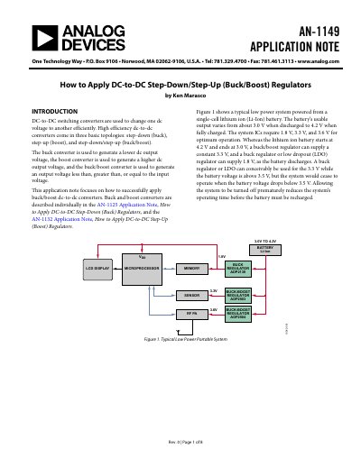
This document is an application note titled "How to Apply DC-to-DC Step-Down/Step-Up (Buck/Boost) Regulators" published by Analog Devices. It focuses on the design and application of buck/boost converters, which can generate output voltages less than, greater than, or equal to the input voltage. The text describes the internal topology of these regulators, which contain four switches, two capacitors, and an inductor, and explains how they operate in buck mode, boost mode, and buck/boost mode to maintain regulation across varying input voltages.
| Input Voltage Range | 2.3 V to 5.5 V |
|---|---|
| Output Voltage Options | Fixed or adjustable via external resistance divider |
| Switching Frequency Range | 500 kHz to 3 MHz |
| Shutdown Current | Less than 1 uA |
It is used to generate an output voltage that is less than, greater than, or equal to the input voltage.
It allows the system to operate down to the minimum practical battery voltage (e.g., 3.0 V), utilizing most of the stored energy compared to a low dropout regulator.
The thermal shutdown circuit turns the regulator off until the on-chip temperature drops below the preset limit.