
This document describes the design, operation, and test of the ADP1822 standard evaluation board. In all tests, the board is operated from an input voltage range of 9V to 15V, and generates up to 10A at VOUT = 1.8V. The switching frequency is fixed at 300kHz.
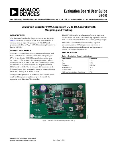
The document provides a user guide for the ADP1822 Evaluation Board (ADP1822-EVALZ), detailing its design, operation, and test procedures. The board operates from an input voltage range of 9 V to 15 V and generates up to 10 A at an output voltage of 1.8 V with a fixed switching frequency of 300 kHz.
| Input Voltage (VIN) | 9 V to 15 V |
|---|---|
| Output Voltage (VOUT) | 1.8 V |
| Switching Frequency | 300 kHz |
| Maximum Output Current | 10 A |
| Current Limit | 15 A |
The frequency is selected via Jumper 1; open for 300 kHz and short for 600 kHz.
The soft start period is set by connecting a capacitor from the SS pin to GND.
A 1% resistor with a value between 1 kΩ and 10 kΩ is recommended.