
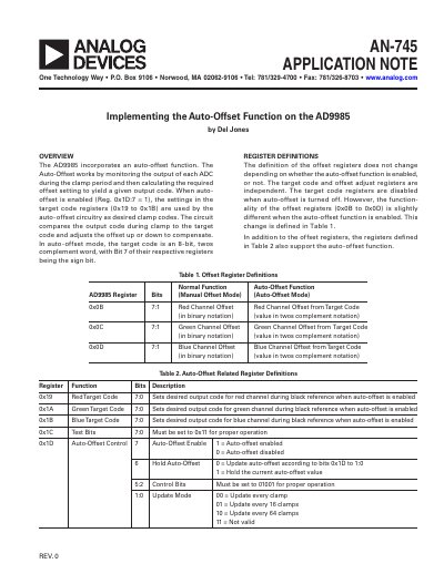
The AD9985 incorporates an auto-offset function. The Auto-Offset works by monitoring the output of each ADC during the clamp period and then calculating the required offset setting to yield a given output code. When auto- offset is enabled (Reg. 0x1D:7 = 1), the settings in the target code registers (0x19 to 0x1B) are used by the auto-offset circuitry as desired clamp codes. The circuit compares the output code during clamp to the target code and adjusts the offset up or down to compensate. In auto-offset mode, the target code is an 8-bit, twos complement word, with Bit 7 of their respective registers being the sign bit.
The document describes the implementation of the auto-offset feature in the AD9985 Analog-to-Digital Converter (ADC). This function monitors the output during the clamp period to calculate and adjust the required offset setting automatically. When enabled via Register 0x1D, the circuit compares the actual output code against target codes set in Registers 0x19 through 0x1B to compensate for signal levels.
The guide provides detailed definitions for offset registers (0x0B to 0x0D) and auto-offset related registers (0x19 to 0x1D), explaining their behavior in both manual and auto-offset modes. It includes specific instructions on programming target codes for RGB and YPbPr signals, setting update modes, and performing brightness adjustments using signed two's complement values.
To activate the function, set Register 1Dh, Bit 7 to 1.
The effective range for adjusting offset is +63 LSBs to -64 LSBs.
For RGB signals, all three registers should normally be programmed to a very small code, such as 4.