
This document is the user guide for the evaluation board of the 7.5 GHz PLL frequency synthesizer. It provides detailed information about the on-board power supplies, OP27, and the connection to an external VCO board.
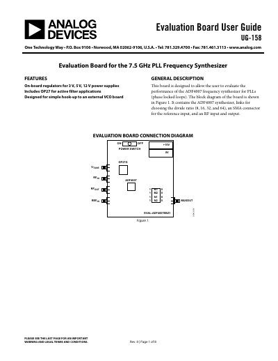
This document is the User Guide (UG-158) for the Analog Devices EVAL-ADF4007EBZ1 evaluation board. The board is designed to allow users to evaluate the performance of the ADF4007 frequency synthesizer for Phase Locked Loops (PLLs). It features an on-board regulator for 3V, 5V, and 12V power supplies and includes an OP27 operational amplifier for active filter applications. The board is designed for simple hook-up to an external VCO board.
| Frequency Synthesizer | ADF4007 |
|---|---|
| Power Supply Voltage | 15 V |
| ADF4007 VDD Voltage | 3.0 V |
| OP27 VCC Voltage | 12 V |
| Max ADF4007 VDD | 3.3 V |
| Reference Input Connector | SMA |
| Output Connector | SMA |
The board is designed to allow the user to evaluate the performance of the ADF4007 frequency synthesizer for PLLs.
The board includes the ADF4007 synthesizer, links for choosing the divide ratio, an SMA connector for reference input, and an RF input and output.
LK1 must be at Position A (Vp is 5 V), M2 at 0 (GND), M1 at 1 (DVDD), N2 at 1 (DVDD), and N1 at 1 (DVDD).
The output frequency should be 10 MHz.