
This document introduces the features and usage of the SSM2167 evaluation board, provides the connection and power supply instructions for the evaluation board, and provides the PCB schematics and layout of the evaluation board.
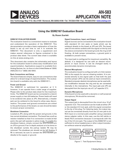
The document provides instructions for using the SSM2167 Evaluation Board to test and understand the operation of the SSM2167 audio processor. It details basic connections for power, ground, shutdown, input signals (electret or dynamic microphones), and output signals.
The guide outlines a five-step testing procedure: establishing connections, configuring the test setup with specific jumper settings, performing listening tests, adjusting noise-gate thresholds, and setting compression ratios. It also includes circuit schematics and a parts list for board modification.
| Operating Voltage | 3 V (optimized) |
|---|---|
| Input Bias Resistor | 2.2 kΩ |
| Output Decoupling Capacitor | 10 μF |
Connect the SHUTDOWN pin on JP3 to ground.
A 2:1 ratio is recommended to start an evaluation.