
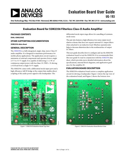
The document provides instructions for configuring the SSM2356 Evaluation Board, covering input/output connections, gain selection via jumpers, emissions limiting modes, and power supply requirements. It details the hardware layout, including header functions and component placement guidelines to minimize EMI.
A step-by-step 'Getting Started' section guides users through setting up the board for testing. The guide also outlines specific parameters to test, such as electromagnetic interference (EMI), signal-to-noise ratio, output noise, maximum power, distortion, and efficiency.
| Supply Voltage Range | 2.5 V to 5.5 V |
|---|---|
| Total Harmonic Distortion + Noise | < 1% |
| Shutdown Current (per channel) | ~20 nA |
| Peak Current (8 Ω, 5V) | approx. 0.33 A |
| Gain Options | 6 dB or 18 dB |
Insert a jumper across header J3 for 18 dB gain, or remove the jumper from J3 to set the gain to 6 dB.
The board accepts a DC power supply between 2.5 V and 5.5 V with correct polarity.