
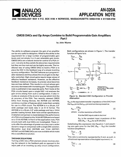
This document describes a method for building programmable gain amplifiers (PGAs) by combining CMOS DACs with operational amplifiers. It details the basic equations for both standard and transposed DAC configurations, explaining how the DAC acts as a programmable resistance or gain element in the feedback loop of an inverting op amp circuit. The text highlights that while this approach allows for a large number of programmable gain levels, accuracy can be limited by DAC linearity and gain errors, particularly at higher gains.
The note specifically analyzes the performance of PGAs based on single DACs, focusing on error sources such as integral linearity and gain error. It provides a rule-of-thumb for estimating percentage gain error based on the required gain and DAC linearity. Additionally, the document compares the performance of circuits using 14-bit and 12-bit DACs and introduces the concept of using dual DACs to achieve greater accuracy over a wider dynamic range.
| AD7534 Package Type | 20-pin, 0.3" wide package |
|---|---|
| AD7534 Loading Format | 8+6 format |
| AD7538 Package Type | 24-pin, 0.3" wide package |
| AD7538 Loading Format | 14-bit parallel loading format |
| AD7528 Resolution | Dual 8-bit |
| AD7537 Resolution | 12-bit |
The DAC is placed in the feedback loop of a simple inverting op amp configuration, where it behaves as a programmable resistance.
The main drawback is that DAC integral linearity causes a rapid deterioration in system accuracy as the gain increases.
Circuits built with dual DACs offer the advantage of greater accuracy over a wider dynamic range.