
The document introduces the reference circuits of Circuit Note CN-0213 Circuits from the Lab™, which are engineered and tested to help solve analog, mixed-signal, and RF design challenges. The devices connected/referenced in the document include AD7685 16-Bit, 250 kSPS PulSAR® ADC in MSOP/QFN, AD8226 Wide Supply Range, Rail-to-Rail Output Instrumentation Amplifier, AD8275 G = 0.2, Level Translation, 16-Bit ADC Driver, ADP1720 50 mA, High Voltage, Micropower Linear Regulator, and ADR439 Ultralow Noise XFET® Voltage Reference. The document also mentions that these circuits have been designed and built by Analog Devices engineers and tested and verified in a lab environment. However, users are responsible for testing the circuit and determining its suitability and applicability for their own use and application.
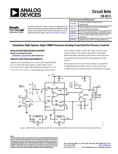
The CN-0213 is a reference circuit designed to process industrial-level signals such as single-ended current (4 mA-to-20 mA), differential voltage, and small signal inputs from sensors like thermocouples or load cells. The circuit utilizes the AD8226 instrumentation amplifier for high precision and input impedance, combined with the AD8275 level shifter/attenuator to drive a 16-bit SAR ADC.
The circuit achieves approximately 105 dB common-mode rejection at 100 Hz and 80 dB CMR at 5 kHz when processing an 18 V p-p input signal.
The AD7685 ADC included in this circuit operates at a sampling rate of 250 kSPS.
The ADP1720 regulator used in this design has a high input voltage range of up to 28 V.