
AN4140 introduces the design considerations of flyback switch power supply transformers, including choosing the right core, determining the current ratio and inductance, calculating switching losses and leakage inductance, determining the gap, designing the primary winding, and designing the secondary winding.
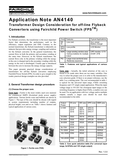
The document explains that the transformer is the most critical factor for flyback converter performance, determining efficiency, output regulation, and EMI. It highlights that flyback transformers function as inductors for energy storage, coupling, and isolation, differing from general transformers where current flows in both windings simultaneously. In flyback applications, current flows only in the primary winding while charging the core, and only in the secondary winding while discharging the core. A gap is typically introduced in the core to increase energy storage capacity.
The note outlines a general transformer design procedure, starting with selecting the proper core type (such as Ferrite) and size based on system requirements like output count, physical height, and cost. It provides a core quick selection table for universal input ranges and 67kHz switching frequencies. The document further details how to determine primary side inductance, calculate the number of turns for each output, and determine the wire diameter based on RMS current and current density.
The current density is typically 5A/mm² when the wire is long.
It is typical to set the ripple factor between 0.5 and 0.7 for the universal input range.
You should avoid using wire with a diameter larger than 1 mm.