
This document provides information about the Motorola MPC561/MPC562 / MPC563/MPC564 RISC MCU, including its high performance CPU system, on-chip watchpoints and breakpoints, program flow tracking, background debug mode, etc.
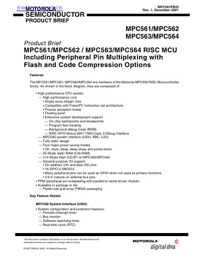
This document is a product brief for the Motorola MPC561, MPC562, MPC563, and MPC564 RISC microcontrollers. These devices are members of the Motorola MPC500 family and feature a high-performance single-issue integer core compatible with the PowerPC instruction set architecture. Key capabilities include floating-point support, extensive system development features such as watchpoints and breakpoints, and four major power-saving modes including deep-sleep and power-down.
The microcontrollers offer flexible memory configurations, with options for 32-Kbyte static RAM (CALRAM) and up to 512-Kbyte flash memory on the MPC563 and MPC564 models. The devices support peripheral pin multiplexing (PPM) and include various integrated modules such as the MPC500 System Interface (USIU), Burst Buffer Controller (BBC), and Queued Analog-to-Digital Converter (QADC64E). Optional features include 56-MHz operation and code compression optimized for automotive applications.
| CPU Core | Single issue integer core compatible with PowerPC instruction set architecture |
|---|---|
| Static RAM | 32-Kbyte |
| Flash Memory | 512-Kbyte (MPC563/MPC564 only) |
| Operating Frequency | 56-MHz (40 MHz default) |
| Interrupts | Up to eight external and 40 internal |
| Address Pins | 24 |
| Data Pins | 32 |
| GPIO | 16 in MIOS14 |
| A/D Channels | Up to 41 total input channels |
The default operation frequency is 40 MHz, with 56-MHz operation available as an optional feature.
Yes, code compression is supported on the MPC562 and MPC564, reducing instruction memory requirements by 40-50%.