
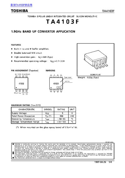
The Toshiba TA4103F is a bipolar linear integrated circuit designed as a silicon monolithic 1.9GHz band up converter. Key features include built-in Local Oscillator (LO) and Intermediate Frequency (IF) buffer amplifiers, along with a double balanced MIX circuit providing high conversion gain of approximately 3dB.
The device operates with a recommended supply voltage between 2.7V and 3.3V. It is housed in an SSOP8-P-0.65 package and weighs typically 0.02g. The datasheet provides detailed electrical characteristics, pin assignments, block diagrams, test circuit information, outline drawings, and maximum ratings for the component.
| Product Type | 1.9GHz Band Up Converter |
|---|---|
| Conversion Gain (Typical) | 3dB |
| Recommended Operating Voltage | 2.7~3.3V |
| Supply Voltage (Max) | 5V |
| Total Power Dissipation | 300 mW |
| Operating Temperature Range | -40~85 °C |
| Storage Temperature Range | -55~125 °C |
| Package Type | SSOP8-P-0.65 |
| Typical Weight | 0.02g |
The recommended operating voltage ranges from 2.7V to 3.3V.
The maximum supply voltage is 5V and the total power dissipation is 300mW.
The operating temperature range is from -40°C to 85°C.