
The document describes a direct replacement for the SILICONIX J/SST174 series P-Channel JFET switch. The product features low on resistance, low gate operating current, etc.
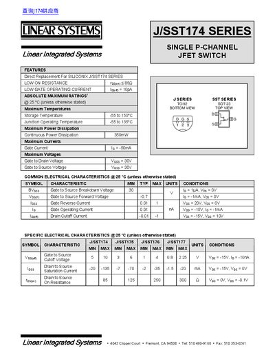
This datasheet details the electrical characteristics and absolute maximum ratings for the J/SST174 series single P-channel JFET switch. It includes parameters such as on resistance, gate operating current, and switching times. The device is designed for direct replacement of Siliconix J/SST174 series components. The datasheet also provides switching circuit parameters and physical dimensions for TO-92 and SOT-23 packages.
| On Resistance | 85 Ω |
|---|---|
| Gate Operating Current | 10 pA |
| Gate to Source Breakdown Voltage | 30 V |
| Gate to Source Forward Voltage | -0.7 V |
| Maximum Power Dissipation | 350 mW |
| Gate to Drain Voltage | 30 V |
| Gate to Source Voltage | 30 V |
| Turn On Time | 10 ns |
| Turn On Rise Time | 15 ns |
| Turn Off Time | 10 ns |
| Turn Off Fall Time | 20 ns |
The on resistance is 85 Ω at Vos = OV, Vos = -0.1V.
The gate operating current is 10 pA.
The gate to source breakdown voltage is 30 V.
The maximum power dissipation is 350 mW.